

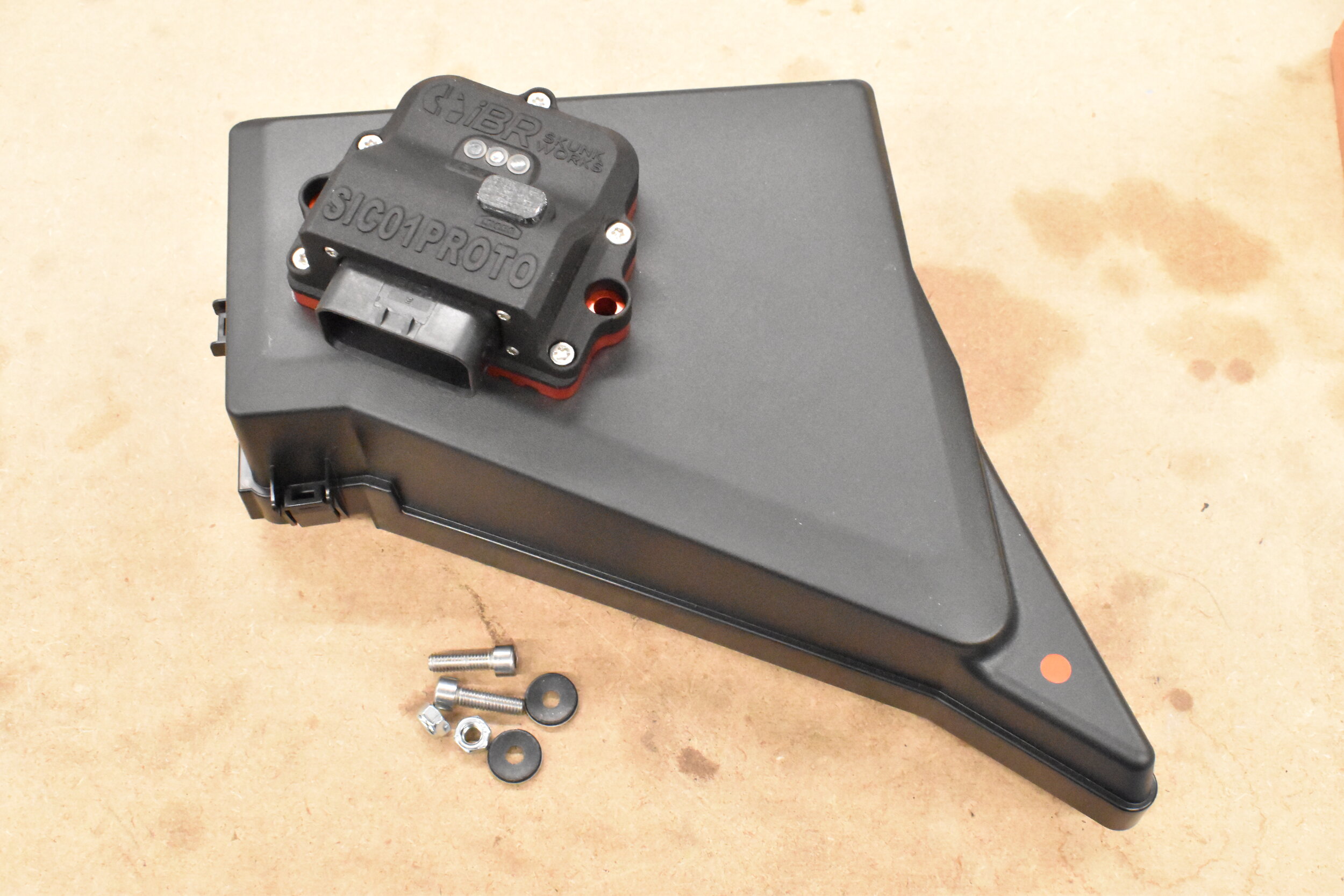
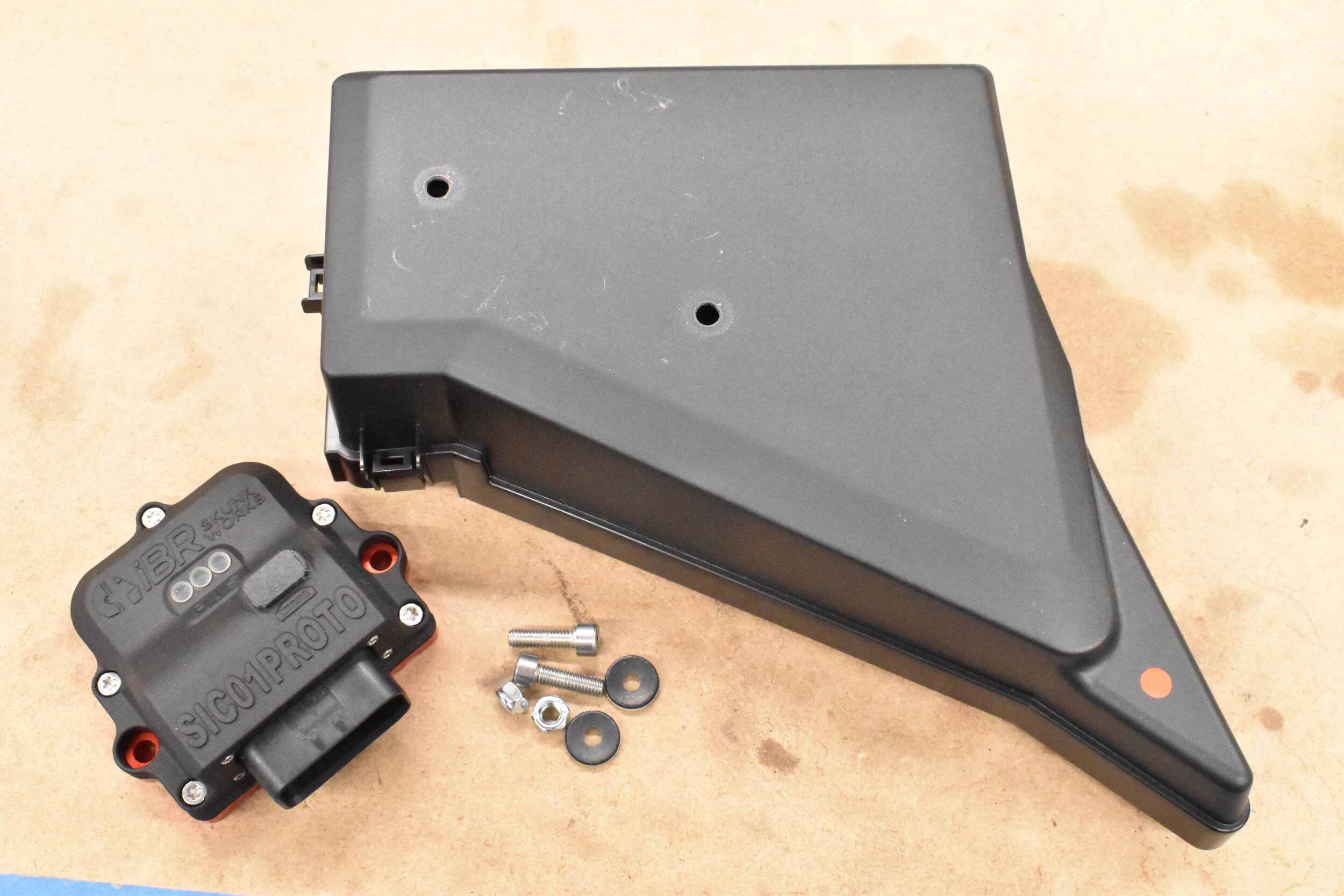
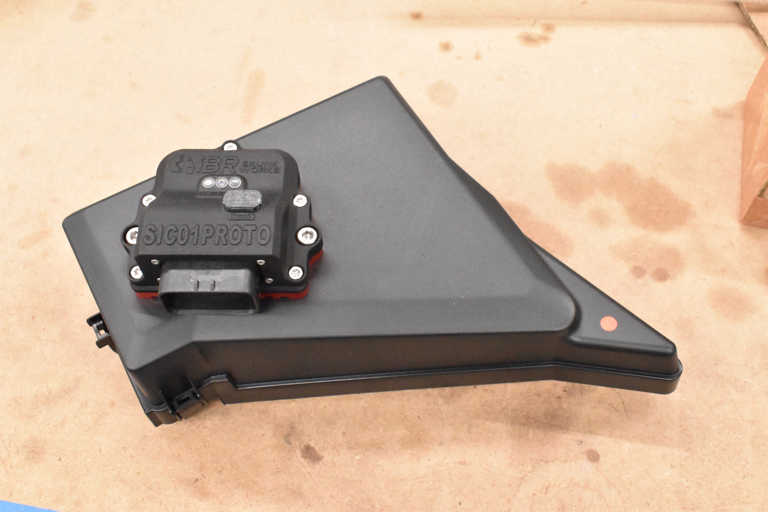
Kit Contents
The iBR Secondary Injection controller kit comes with the SIC01 Injector Controller, SIC FA20DIT Plug-and-Play harness and hardware for mounting the SIC01 to the fuse box cover. See image for contents as it comes in the kit.
A quick note about the images in here….. This is our test mule, the car we put miles on to test our products. It is far from a garage queen and doesn’t get the level of cleaning and attention it probably deserves. Bare with us when we take pictures of our well used/abused/loved car. We are out there driving it and using it just like you. Maybe the guy in the red WRX that waves back will be one of us!


Required Tools
The tools for this job are quite simple.
10mm Socket and ratchet
1/4” Diameter Drill Bit (and drill)
Cutting Pliers (only needed if used on iBR Intake Manifold)
Zip Ties
Mounting SIC01 to Fuse Box Cover
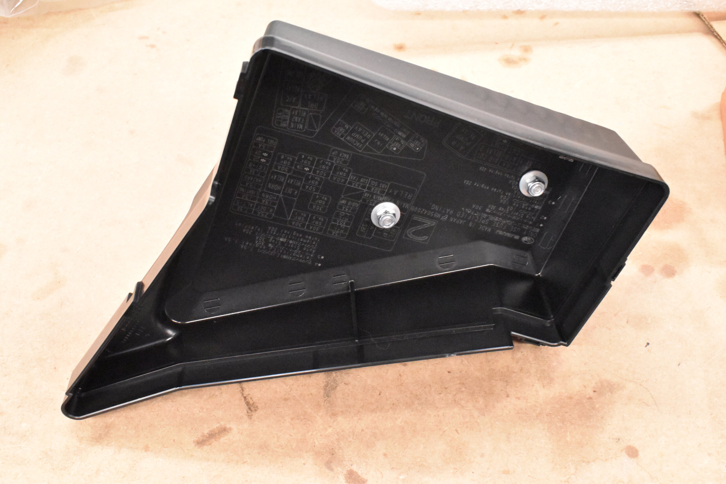
We found the best place to mount this is directly to the top of the fuse box cover. This makes it easy to install/uninstall, easy to see the LEDs and the wiring seems to tuck in and run nicely. Also the cover is ~$12 from your local Subaru dealer so we don’t feel bad about putting a couple holes in it. We did this on a work bench to make life easier.
Line Up SIC01 on Fuse Box Cover
Mark Hole Locations
Drill Holes
Bolt SIC01 to Fuse Box Cover
Use Sealing Washers under the provided nuts to ensure everything is still water resistant
Wiring Installation
STEP 1: Disconnect Power
First thing that should always be done when working on a car is to disconnect the negative terminal on the battery.
This requires a 10mm socket and ratchet. You could also use a 10mm wrench.

STEP 2: Connect SIC01 Chassis Ground
With the fuse box cover removed you can easily see the chassis ground. Locate the black wire with a ring terminal on the harness. This is the main power ground for the SIC01. This is the ground that allows power to be conducted through the injectors.


STEP 3: Reinstall Fuse Box Cover
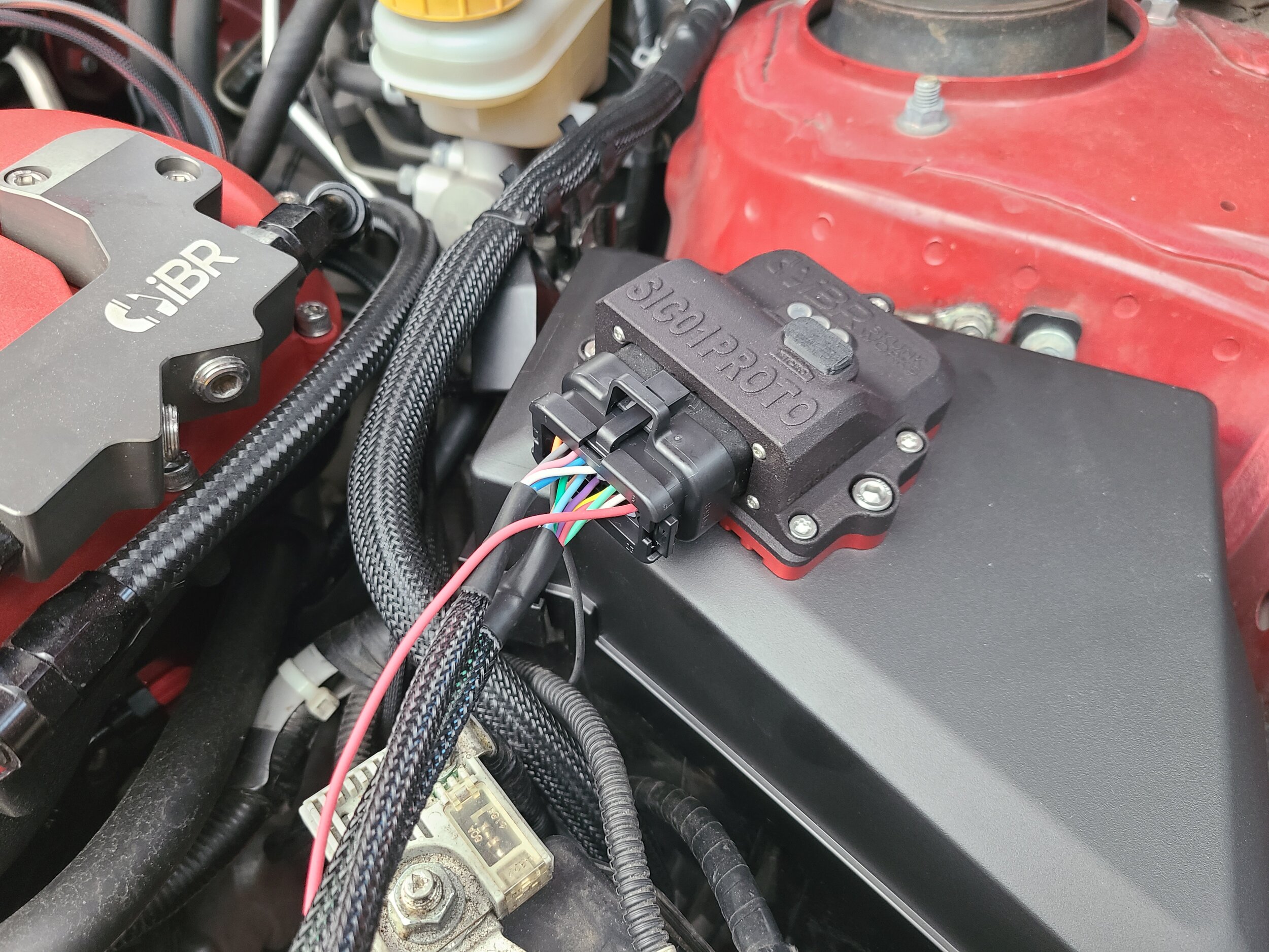
We will now reinstall the fuse box cover on which we have already attached the SIC01. Connect the wiring harness to the SIC01.
This just helps to lay out the wiring and see how we can route the wiring for a nice clean install. We will not go into too much detail on exactly how its routed and zip tied. This will end up being determined a lot by what manifold you have and what other performance parts and OEM parts you have installed/uninstalled.
STEP 4: Routing Direct Injector Signal Wires
Locate the Direct Injection Signal Wires in the Harness. The wiring will be Pink and Blue and the Connectors will look just like the OEM Direct Injector Harness Plug and the actual connector on the Direct Injector. You will want to run this bundle of wires down along the OEM wiring going to the fuse box and behind the intake manifold. The TGV connection is also part of this bundle and we will get to that connection soon.
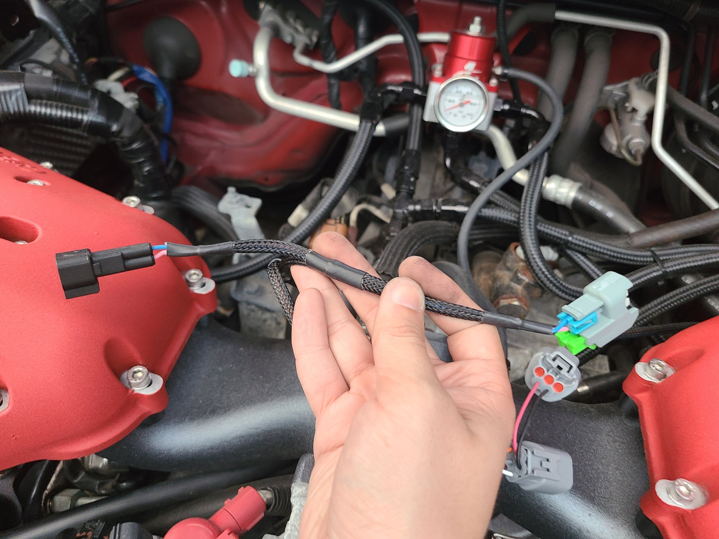
Connect the SIC01 Direct Injection Signal Wires inline with the Cylinder 3 Direct Injector. Cylinder 3 is on the passenger side towards the back of the car. This is reasonably easy to get to by reaching around the back of the intake manifold. Disconnect the OEM injector plug, connect gray harness connection and connect OEM injector plug into the black connector. First image shows the factory injector and the harness plug once it has been removed. The second shows the SIC01 Harness connected inline.


STEP 5: TGV Power and Analog Out Connection
Locate the TGV connector wires on the SIC01 Harness. This will connect inline with the passenger side TGV connector. If you are required due to emissions regulations to still have TGVs in place we have included the pass through wires to keep the TGV motors functional.
This connector sends 5V ECU power to the SIC01 and also connects the analog output of the SIC01 to the TGV position sensor input. The duty cycle of the SIC01 can be monitored by recording or displaying the right hand (passenger) TGV voltage. See the link on the main product page for the SIC01 technical specification for the output curve. The 5V connection on this plug is also what turns on the SIC01 when you turn the car on. As soon as the car is turned on +12V will be supplied to each of the secondary injectors then the SIC01 will switch the ground side to turn them on. This is a common method of control in most OEM applications.


STEP 6: Connecting the Secondary Injectors
The order and location of the injectors that are connected to the SIC01 is not important. We did design the harness to be install in a way to give proper isolation to the engine though. We designed the injector wires to wrap back along with the OEM wires towards the back of the intake manifold then run the drivers side wires forward with the shortest injector connection going to the drivers side rear injector then the next longer plug on that section of the harness going to the drivers side front injector. The same goes for the passenger side injectors, run the length of the wires behind the manifold along the factory harness and start with the sorter of the two connectors going to the rear injector and the longer going towards the front.
The first image shows the harness being attached and the wiring out in the open so you can see. The second image shows how the wires can be run under and along the the fuel system to help hide and protect the wires. Make sure there is enough slack going back to the SIC01 on all wires so that when the engine moves under normal driving conditions the wires don’t pull on the SIC01 harness connection.
Wires left exposed to show connections

Wires tucked and run properly
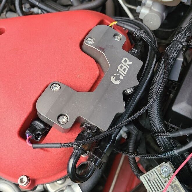
*If you are running the iBR Intake Manifold the injector connectors must be trimmed slightly. We attempted to create the best flow around bell mouths at the top of the runners so we had to minimize the injector pockets to where they were functional but very tight fit! We may have gone too far but it was all in the quest for the best possible performance. See bottom of page for trimming instructions.
STEP 7: SIC01 +12V Power
We always leave the final power connection for last. Remove the red plastic cover (if you still have it) on the positive terminal of the battery. Under that cover is a 10mm nut where we are going to install the 12V power connection. Find the ring terminal on the red fused wiring coming from the SIC01 harness. Connect as shown then bend the wiring down along the OEM wire to allow for refitting the red plastic cover.
This would also be a good time to go ahead and re-connect the ground connection on the negative battery terminal.
Wiring of the SIC01 is complete!


Startup and Basic Functional Testing
Once you have double checked all of your wiring make sure to go through and zip-tie everything in place and ensure none of the wires are tensioned or being pulled. You want to make sure that the SIC01 harness has enough slack between the main connector and the engine so that any movement will not pull on the SIC01 housing.
The first functional test we are going to do is to turn the car to the ON position but DO NOT START THE CAR
You should see:
“P” (Power) LED light up green
”I” (Input) LED light up yellow
”S” (Status) LED light up green
This means that the module as good 5V and 12V power (P->green), it is waiting for a direct injection event (I->Yellow) and there are not other pending errors (S->Green).
For troubleshooting these LED status indicators please refer to our technical documentation that is linked on the main product page.

The second functional test we are going to do is to turn the car to the ON position and START THE CAR
You should see:
“P” (Power) LED light up green
”I” (Input) LED light up green
”S” (Status) LED light up green
This means that the module as good 5V and 12V power (P->green), it is reading direct injection events (I->Green) and there are not other pending errors (S->Green).
For troubleshooting these LED status indicators please refer to our technical documentation that is linked on the main product page.

Final Important Notes
At this point you have the SIC01 installed and FUNCTIONAL but your car will NOT be tuned for it. We recommend to disconnect just the four secondary injectors from the SIC01 harness so that you do not accidentally engage the secondary injection before you are ready to tune. With the secondary injectors disconnected and your car having a proper tune you can drive your car up into a high load (above 4krpm or so and peak boost). During the pull you can log or view your right hand TGV position voltage. At high loads you should see the SIC01 starting to activate (reading above 0.5V) but since the injectors are not connected it won’t affect your current fuel mapping. The point at which the SIC comes on will depend on your existing tune, peak boost and ethanol content. To understand the voltage output and what it means please read our technical document linked on the main product page.